
Design Smarter Building Comfort with Variable Refrigerant Flow Zoning Across Virginia
Whitescarver Engineering
How VRF Zoning Keeps Virginia Commercial Spaces Comfortable
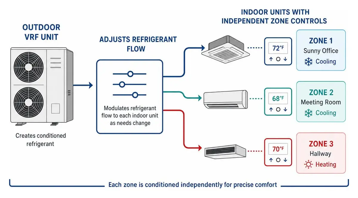
VRF zoning gives each area its own temperature control. To plan it well, start with the heating and cooling needs of each space, then place an indoor unit and controls where loads differ. The system adjusts refrigerant flow as those needs change. For a facility manager in Roanoke, VA, this can help a sunny office, a busy meeting room, and a quiet hallway stay comfortable without treating them as one zone. VRF zoning also needs a ventilation plan and controls that meet Virginia's commercial energy code. Good design brings those pieces together from the start.
Explore how VRF systems work, or contact Whitescarver Engineering Co. about your building.
How VRF Systems Provide Precise Zoning for Commercial Buildings in Virginia
Commercial structures throughout Virginia present complex thermodynamic challenges. A corner conference room flooded with southern sunlight requires active cooling at the same time an interior core server room generates steady heat and shaded northern perimeter offices demand heating. Understanding how a variable refrigerant flow VRF system operates clarifies how modern mechanical design resolves these conflicting thermal profiles.
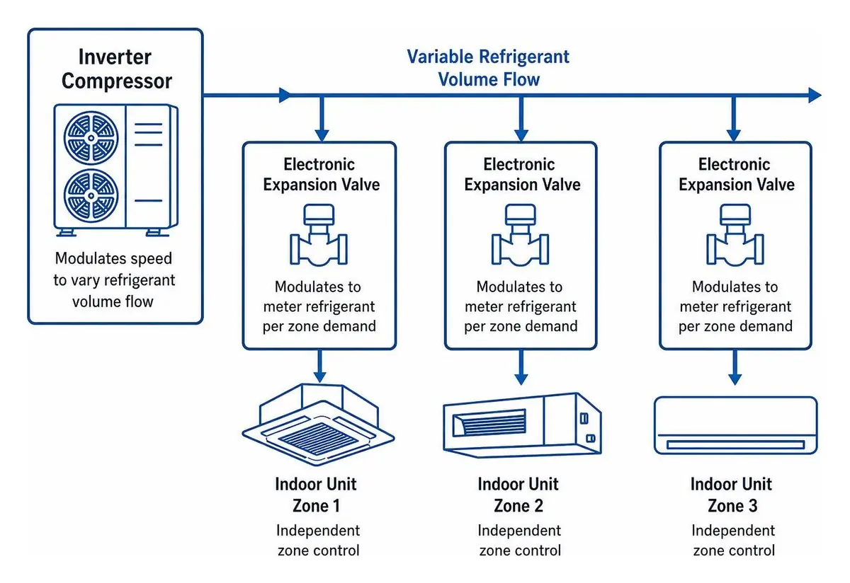
Unlike traditional commercial systems that rely on large central air handlers and fixed-volume duct networks, VRF technology decentralizes temperature management. The heart of the system relies on an outdoor condensing unit equipped with one or more inverter-driven compressors. These variable-speed compressors continuously modulate motor frequency, altering the volume of refrigerant circulated through the piping network to match real-time thermal loads.
Inside the facility, each distinct microclimate or architectural zone features an individual indoor terminal unit—such as a ceiling cassette, concealed ducted fan coil, or wall-mounted unit. Each indoor terminal is paired with an electronic expansion valve (EEV). By adjusting valve pin positions in micro-increments, the system meters the exact mass flow of refrigerant needed to satisfy the active setpoint of that specific space.
In heat recovery configurations, this architecture enables simultaneous heating and cooling. Utilizing branch selector boxes, the system extracts waste heat from cooling-dominated areas and redirects thermal energy across the refrigerant loop to zones calling for heat. By shifting thermal energy internally rather than rejecting it outside, building operators eliminate the energy waste inherent in old-fashioned single-duct systems.
Resolving Air Distribution Losses and Damper Hunting
Traditional constant-air-volume (CAV) and variable-air-volume (VAV) architectures often struggle when tasked with tight zone control. When typical VAV systems attempt to balance diverse spaces, terminal bypass dampers or throttling air valves frequently oscillate, a condition known as damper hunting. This creates pressure imbalances, noisy air velocity fluctuations, and significant fan energy losses.
VRF systems equipped with modulating dampers or dedicated ductless terminal coils eliminate bypass duct requirements entirely. By resolving chronic commercial zoning problems at the fluid level rather than forcing excessive air volume through bypass runs, static pressure within ducted runs remains exceptionally stable.
According to standard fan affinity laws, fan power varies with the cube of fan speed. A 20% reduction in fan speed yields an approximate 49% reduction in fan power consumption. By matching airflow directly to thermal load at the individual zone coil, part-load performance is maximized while acoustic disturbance in occupied tenant suites is minimized.
Centralized Building Automation and Intelligent Zone Management
Modern commercial zoning depends on robust communication between field devices and central supervisors. Contemporary commercial HVAC control architectures seamlessly bridge proprietary VRF protocols with open protocols such as BACnet MS/TP or BACnet/IP.
Using native communication gateways, facility engineers can view granular telemetry across every terminal unit, including:
- Real-time room air temperature versus setpoint
- Electronic expansion valve opening percentage
- Suction and liquid line refrigerant temperatures
- Error codes and run-hour logs
Integrating these devices into a building-wide network illustrates how building automation systems optimize energy usage. Centralized management permits global scheduling, demand-limiting routines during peak grid hours, and automated setpoint clamping to prevent unauthorized occupant adjustments across different commercial suites.
Aligning VRF Zoning with the 2018 Virginia Energy Conservation Code (VECC)
Commercial construction in the Commonwealth must adhere to the 2018 Virginia Energy Conservation Code (VECC), which references ASHRAE Standard 90.1. Section C403 establishes strict requirements for mechanical efficiencies, system controls, and part-load operations. Evaluating these criteria is vital when evaluating chillers versus rooftop units and VRF systems for Virginia facilities.
| System Metric / Code Requirement | Traditional Constant Volume RTU | Central Chilled Water / VAV | Multi-Zone VRF Heat Recovery |
|---|---|---|---|
| Zoning Granularity | Single broad zone per unit | Zone per VAV terminal box | Independent micro-zone per indoor unit |
| Simultaneous Heat/Cool | Not possible without reheat | Reheat coils (energy penalty) | Direct thermal energy exchange via branch boxes |
| Minimum Efficiency Baseline | 2018 VECC Section C403.2.3 | VECC Table C403.2.3(1-7) | VECC Table C403.2.3(13) (11.0 EER / 12.0 IEER or higher) |
| Part-Load Modulation | Staged cycling (high losses) | Variable frequency drives on chillers/fans | Inverter compressor down to less than 15% total capacity |
| Air Leakage Risk | Extensive supply/return ducting | Extensive supply duct network | Minimal or ductless refrigerant piping runs |
Under Section C403.2.3, air-cooled VRF systems with capacities equal to or greater than 65,000 Btu/h must meet stringent minimum efficiency baselines (such as 11.0 EER and 12.0 IEER for heat recovery systems). The inverter compressor's capacity to ramp down to a fraction of its rated output ensures compliance during the intermediate spring and autumn seasons typical in Virginia.
Mandatory Thermostatic Controls, Deadband, and Setback (Section C403.2.4)
Section C403.2.4 governs HVAC system controls. Key provisions directly impacting multi-zone mechanical layouts include:
- Thermostatic Controls (C403.2.4.1): Each distinct zone must be equipped with an individual thermostatic controller.
- Deadband Requirements (C403.2.4.1.2): Where heating and cooling are controlled by the same system, the controller must enforce a minimum deadband of 5°F (2.8°C). This deadband prevents the system from oscillating between cooling and heating modes within a narrow temperature window.
- Off-Hour Setback Controls (C403.2.4.2): Systems must incorporate automatic start, setback, and shutdown capabilities with programmable weekly schedules and minimum 7-day retention during power loss.
Modern VRF master controllers enforce these constraints natively at the hardware level, demonstrating the tangible benefits of modern commercial HVAC controls by maintaining tight temperature stability while locking out illegal setpoint overlaps.
Economizer Integration and Fault Detection and Diagnostics (Section C403.2.4.7)
Where mechanical designs incorporate air economizers under prescriptive section C403.3, Section C403.2.4.7 requires mandatory Economizer Fault Detection and Diagnostics (FDD) on systems serving individual zones.
The FDD system must monitor key system parameters via high-precision temperature sensors rated to within plus or minus 2°F (plus or minus 1.1°C). The diagnostic platform must actively verify and report:
- Free cooling availability status
- Economizer damper position feedback (open, modulating, or closed)
- Air temperature sensor failures
- Excess outdoor air intake during mechanical cooling
- System failure to switch to economizer mode when outdoor ambient enthalpy is favorable
When VRF systems operate alongside centralized air handling systems utilizing economizers, connecting FDD outputs directly into the supervisory building management system guarantees rapid notification of damper binding or sensor drift, preventing thermal loss.
Dedicated Outdoor Air Systems (DOAS) and Energy Recovery (Section C403.2.7)
Because VRF systems condition zone air through decentralized terminal units, fresh outdoor ventilation must be provided through a decoupled Dedicated Outdoor Air System (DOAS).
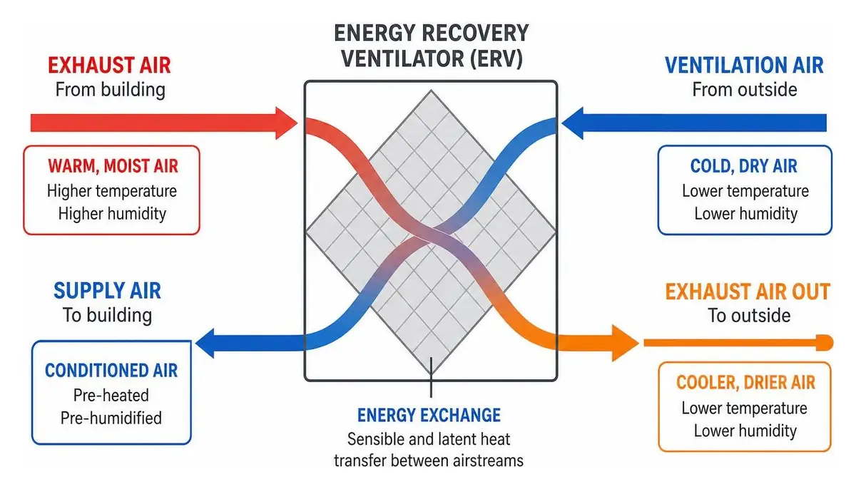
Section C403.2.7 mandates Energy Recovery Ventilation (ERV) for fan systems meeting specific design airflow and outdoor air percentages. In Virginia's mixed-humid climate (Climate Zones 4A and 5A), unconditioned ventilation air introduces high sensible and latent moisture loads during summer months.
Integrating an ERV wheel or enthalpy plate exchanger allows incoming outdoor air to exchange total energy with building exhaust air. This reduces the entering wet-bulb temperature during humid summers and pre-heats incoming sub-freezing air during winter, stabilizing the sensible and latent load before air reaches individual VRF indoor zones. This design methodology is essential when handling Virginia summer humidity and winter cold snaps.
Envelope Performance Synergy and Mechanical Sizing Under Section C402
A commercial building's thermal envelope directly influences mechanical zoning granularity. Section C402 of the 2018 VECC establishes strict maximum U-factors for opaque wall assemblies and fenestration systems.
Engineers evaluating compliance can utilize either the prescriptive table method or the Component Performance Alternative (Section C402.1.5), which permits trade-offs between assembly U-factors, C-factors, and F-factors. The total heat loss through the proposed building envelope must not exceed the total heat loss allowed by the code's budget envelope.
By elevating continuous insulation levels on exterior walls (such as utilizing staggered-joint polyisocyanurate continuous board under Section C402.2), external thermal swings are mitigated. This reduction in outer thermal transfer flattens the peak load of perimeter spaces, allowing the indoor VRF terminal units in those zones to run at lower, more efficient part-load compressor states.
Designing How VRF Systems Provide Precise Zoning for Commercial Buildings in Virginia Under Energy Codes
Under Section C403.2.1, all heating and cooling loads must be calculated in strict compliance with ASHRAE Standard 183 or equivalent ACCA Manual N engineering procedures. This analytical step explains in technical detail how vrf systems provide precise zoning for commercial buildings in virginia by preventing unit oversizing.
Section C403.2.2 prohibits over-sizing equipment beyond calculated design loads, with narrow exceptions for standard increment sizing. Traditional HVAC systems designed to peak block loads frequently suffer from short-cycling at part-load conditions, causing poor humidity control and temperature swings.
With VRF systems, engineers size indoor terminal units based on the peak sensible and latent load of each individual zone, while the outdoor condensing unit is sized based on the building’s diversified coincident block load. Because perimeter zones receive peak solar radiation at different hours of the day, diversity factors of 110% to 130% indoor-to-outdoor unit connection ratios are routinely achieved, maximizing capital equipment utility.
Solar Heat Gain, Continuous Insulation, and Daylight Zones
Fenestration performance heavily dictates zoning stability. Section C402.4 restricts vertical fenestration area to a maximum of 30% of the gross above-grade wall area, though this area can be expanded up to 40% when combined with daylight-responsive controls under Section C402.4.1.1 and Section C405.2.3.
Large glazed areas exhibit rapid solar gain spikes in morning (east facades) and afternoon (west facades). Sidelit daylight zones paired with dimmable LED fixtures reduce interior sensible lighting heat gains as outdoor sunlight increases. The local VRF indoor unit responds via its onboard return air thermistor and EEV positioning, throttling down cooling output proportionally to balance the net heat gain, maintaining steady room conditions without over-cooling adjacent shaded offices.
Commercial Facility Applications Across Virginia
The physical layout, internal heat gains, and occupancy profiles of commercial facilities dictate their mechanical requirements. The right zoning strategy directly influences how comprehensive HVAC design directly affects occupant and tenant comfort.
How VRF Systems Provide Precise Zoning for Commercial Buildings in Virginia by Space Type
Different commercial facilities benefit from targeted VRF configurations:
- Commercial Office Buildings: Core spaces with steady computer loads require continuous cooling, while exterior perimeter suites transition from morning heating to afternoon cooling. A heat recovery VRF configuration balances these thermal demands simultaneously without burning auxiliary fossil fuels.
- Conference Suites and Training Rooms: High-density occupant surges create rapid sensible heat and carbon dioxide (CO2) spikes. Paired with demand-controlled ventilation (DCV) under Section C403.2.6.1, indoor VRF units ramp cooling instantly upon occupancy detection.
- Hospitality and Multi-Family: Individual guest suites operate on completely independent schedules. When evaluating options, comparing VRF technology with traditional rooftop units reveals that VRF isolates noise, prevents cross-space odor transfer through shared ducts, and allows individual guest thermostatic authority.
- Educational Facilities: Classrooms alternate between fully occupied and vacant states. VRF terminal scheduling linked to master occupancy sensors ensures unoccupied rooms enter deep setback modes without disrupting comfort in administrative offices.
Refrigerant Safety Management and ASHRAE Standard 15 Compliance
Because VRF systems distribute refrigerant piping throughout occupied building spaces, mechanical engineers must ensure life safety compliance with ASHRAE Standard 15 (Safety Standard for Refrigeration Systems) and ASHRAE Standard 34 (Designation and Safety Classification of Refrigerants).
The critical design factor is the Refrigerant Concentration Limit (RCL). The total mass of refrigerant in a single, interconnected closed circuit divided by the smallest enclosed, occupiable room volume served by that circuit must remain below the RCL threshold. In practical terms, the refrigerant concentration in pounds per cubic foot must not exceed the safety limit established for the specific refrigerant type.
As modern commercial equipment transitions to lower-GWP A2L refrigerants (such as R-454B or R-32), designers implement practical engineering safety measures:
- Designing multiple, smaller independent refrigerant piping circuits rather than one single massive loop
- Installing ducted fan coil units in ceiling plenums to expand effective room air volume
- Integrating automated refrigerant leak detection sensors connected to motor-operated branch isolation shutoff valves
Frequently Asked Questions About Commercial VRF Zoning in Virginia
How do heat recovery VRF systems manage simultaneous heating and cooling across different zones?
Heat recovery VRF systems utilize a three-pipe or engineered two-pipe distribution architecture linked to intermediate branch selector (BS) boxes. When an indoor zone calls for cooling, the indoor unit acts as an evaporator, absorbing heat from the room and boiling liquid refrigerant into low-pressure gas.
Instead of venting this thermal energy outdoors via the condenser, the branch selector redirects the superheated gas to zones calling for heating. In those heating zones, the indoor unit acts as a condenser, releasing the captured thermal energy into the occupied space. This thermal transfer dramatically cuts total electrical consumption.
What specific load calculation methods must engineers follow for VRF zoning under Virginia codes?
Mechanical systems designed under the 2018 VECC Section C403.2.1 must execute load calculations using procedures defined in ASHRAE Standard 183 or an equivalent computational methodology. The designer must calculate:
- Zone Peak Loads: Sizing each indoor terminal unit to meet the peak sensible and latent cooling and heating demands of its dedicated space.
- Block Load Analysis: Sizing the outdoor condensing unit based on the diversified coincidence of all indoor units combined.
- Decoupled Ventilation Loads: Calculating the sensible and latent ventilation air treatment separately when utilizing a Dedicated Outdoor Air System (DOAS).
How does integrating a BAS enhance VRF zone performance in commercial facilities?
Integrating a Building Automation System (BAS) via BACnet or Modbus gateways centralizes operational oversight. Facility teams can track real-time compressor lift, evaluate individual zone temperature trends, and enforce building-wide setback schedules during unoccupied hours.
For large-scale commercial facilities, utilizing building automation systems to maximize overall HVAC efficiency enables automated load shed routines during utility peak billing periods, fault alerting before occupants register comfort complaints, and seamless integration with lighting and access control platforms.
Conclusion
Variable Refrigerant Flow (VRF) technology delivers localized thermal comfort, architectural flexibility, and energy efficiency for commercial buildings across Virginia. By utilizing inverter-driven compressors, electronic expansion valves, and intelligent heat recovery capabilities, VRF systems meet the rigorous demands of the 2018 Virginia Energy Conservation Code while maintaining stable interior comfort across every season.
Achieving peak performance requires careful mechanical engineering—from compliant load calculations and ASHRAE Standard 15 refrigerant management to continuous insulation coordination and dedicated outdoor air design.
Whitescarver Engineering Co. has provided commercial and industrial HVAC and refrigeration engineering, installation, and maintenance across Roanoke, Salem, Vinton, and the Blacksburg/Christiansburg corridor since 1937.
To discuss your facility’s mechanical layout, explore complete VRF system engineering and implementation or reach out to our team of engineers to optimize your building's comfort and energy performance.
Facility intake
Need Help?
Tell us what facility, system, or maintenance risk needs attention so the first conversation starts with useful context.
About the Author
Whitescarver Engineering
Related Posts
- How VRF Systems Handle Virginia’s Hot Summers & Cold Winters
- The Ultimate Guide to Chiller vs Rooftop Unit vs VRF for Virginia Commercial Facilities
- Commercial HVAC Controls Integration for Virginia Energy Conservation and Peak Efficiency
- Keep Your Operations Online by Investing in Routine Commercial HVAC Care
- How to Plan a Phased Commercial HVAC Upgrade Without Business Disruption in Virginia
Related service: Commercial HVAC
Related Articles
Engineering-led support
Ready to Get Started?
Whether you need a repair, maintenance, or a new installation, our expert team is here to help.